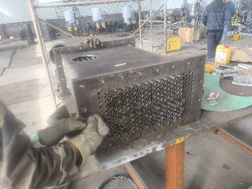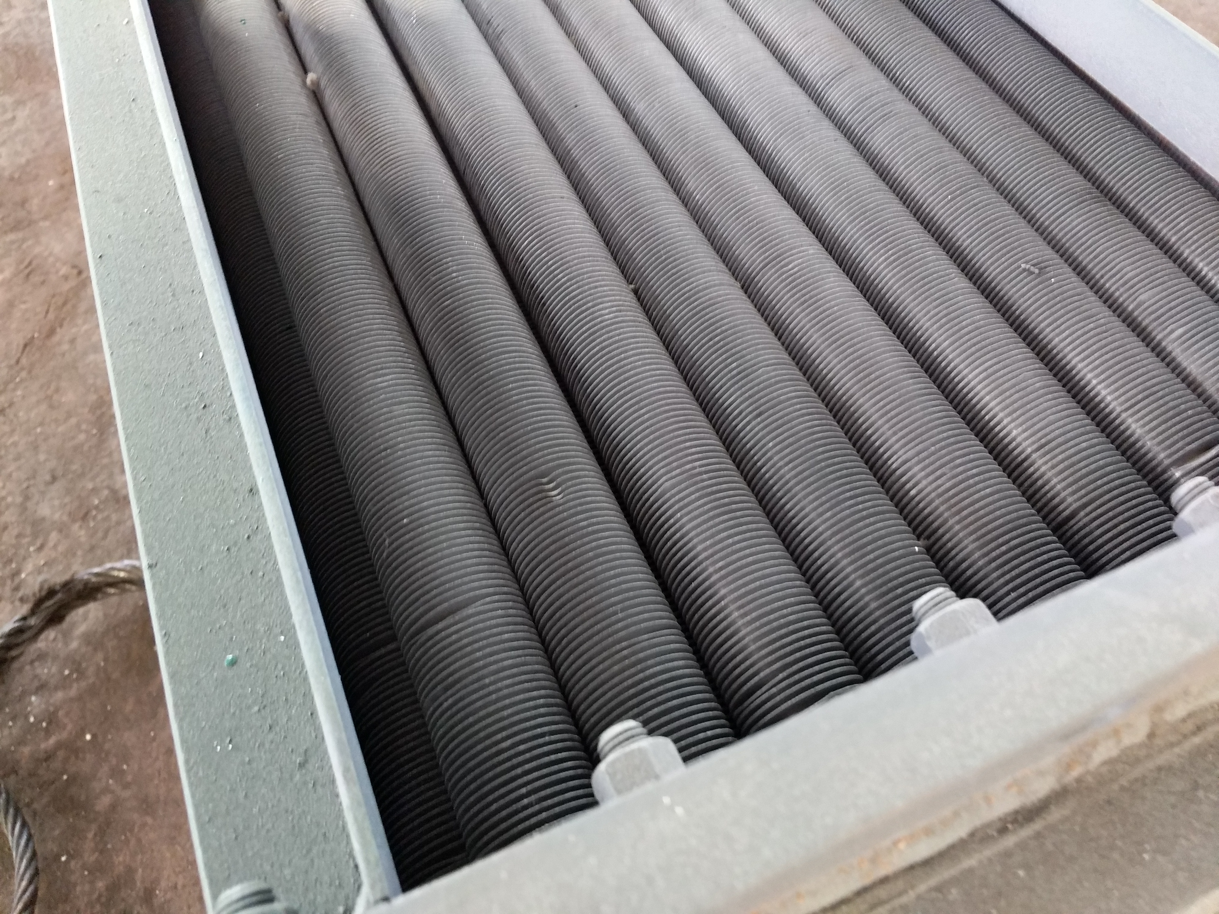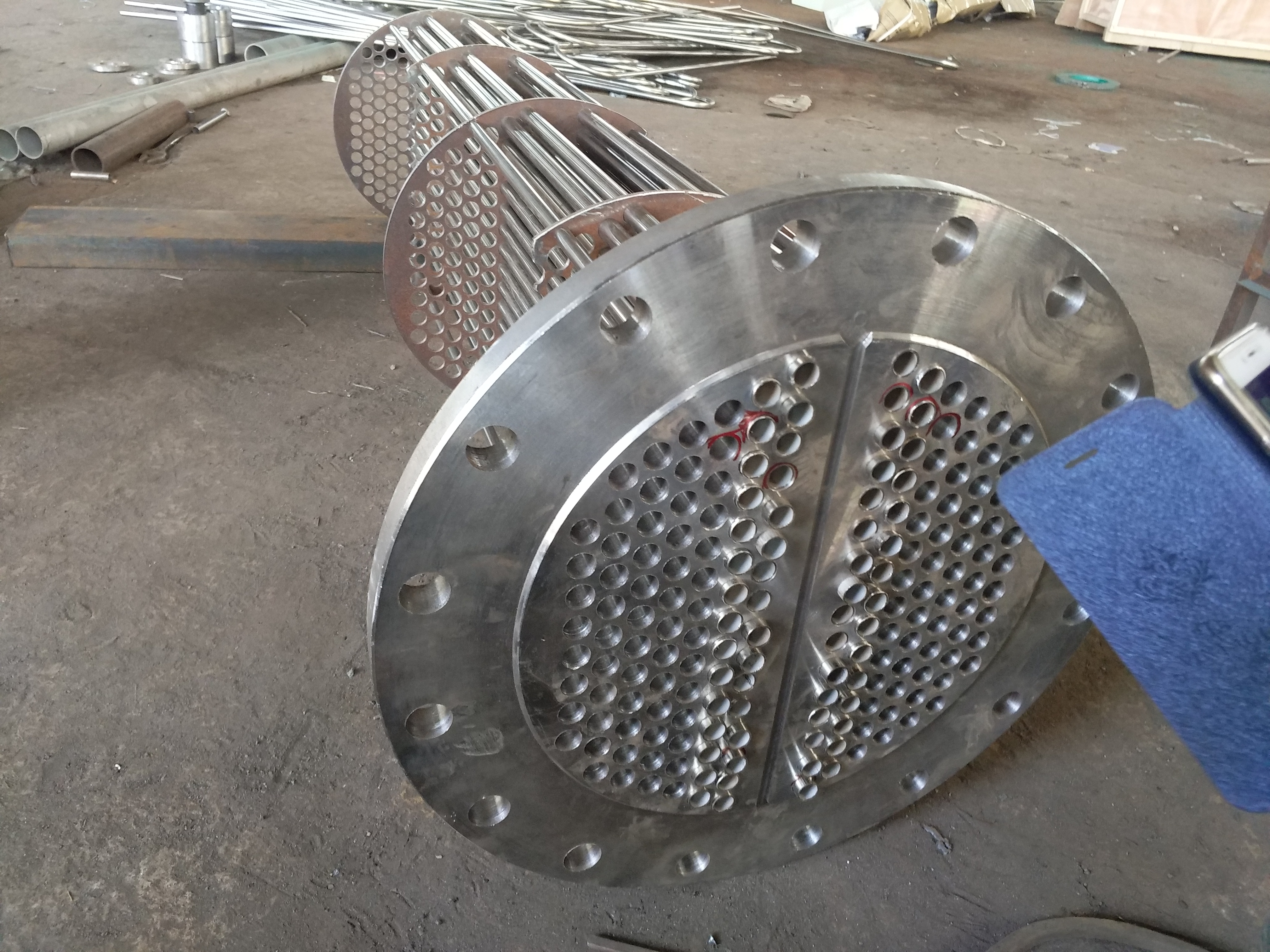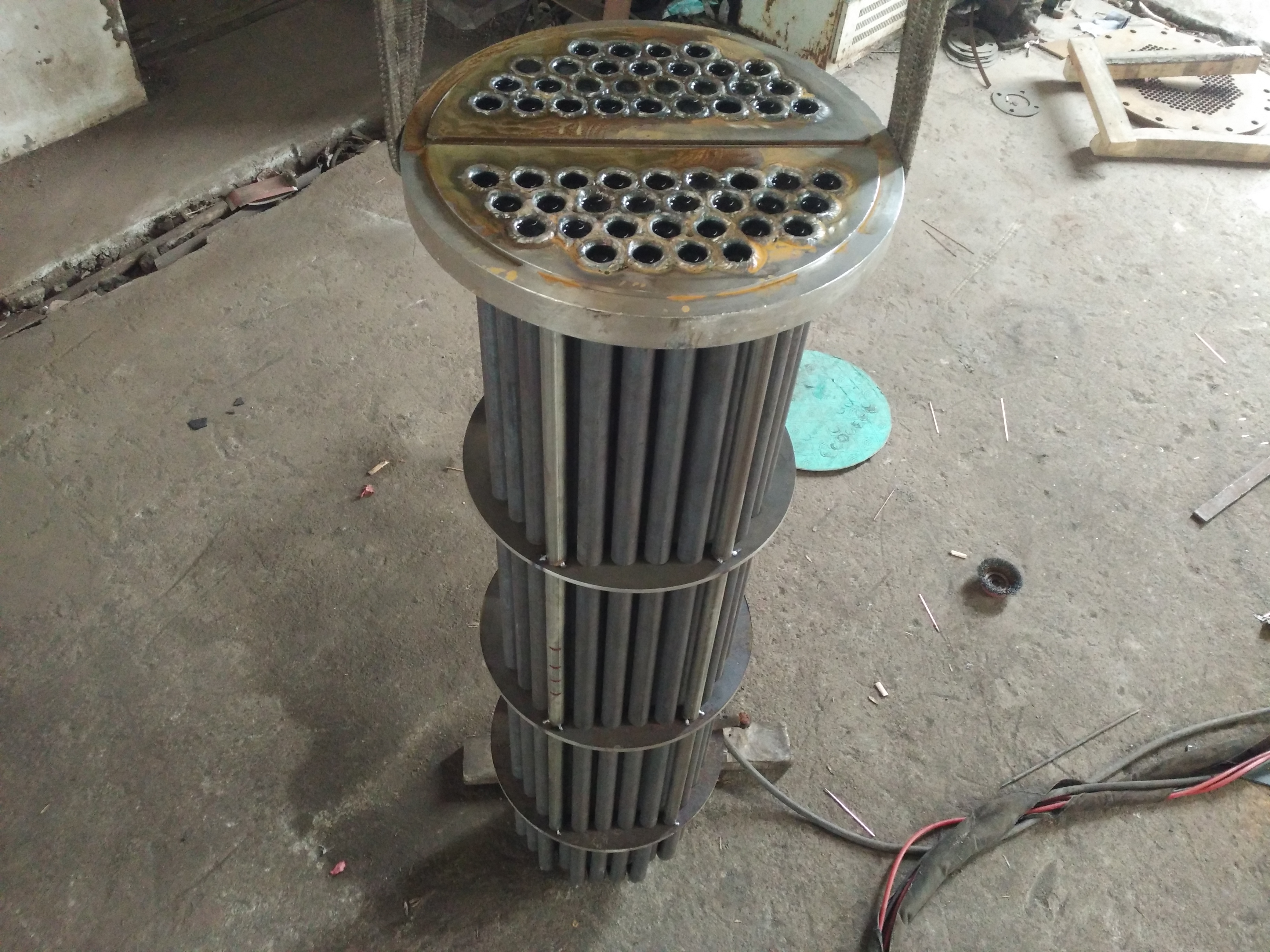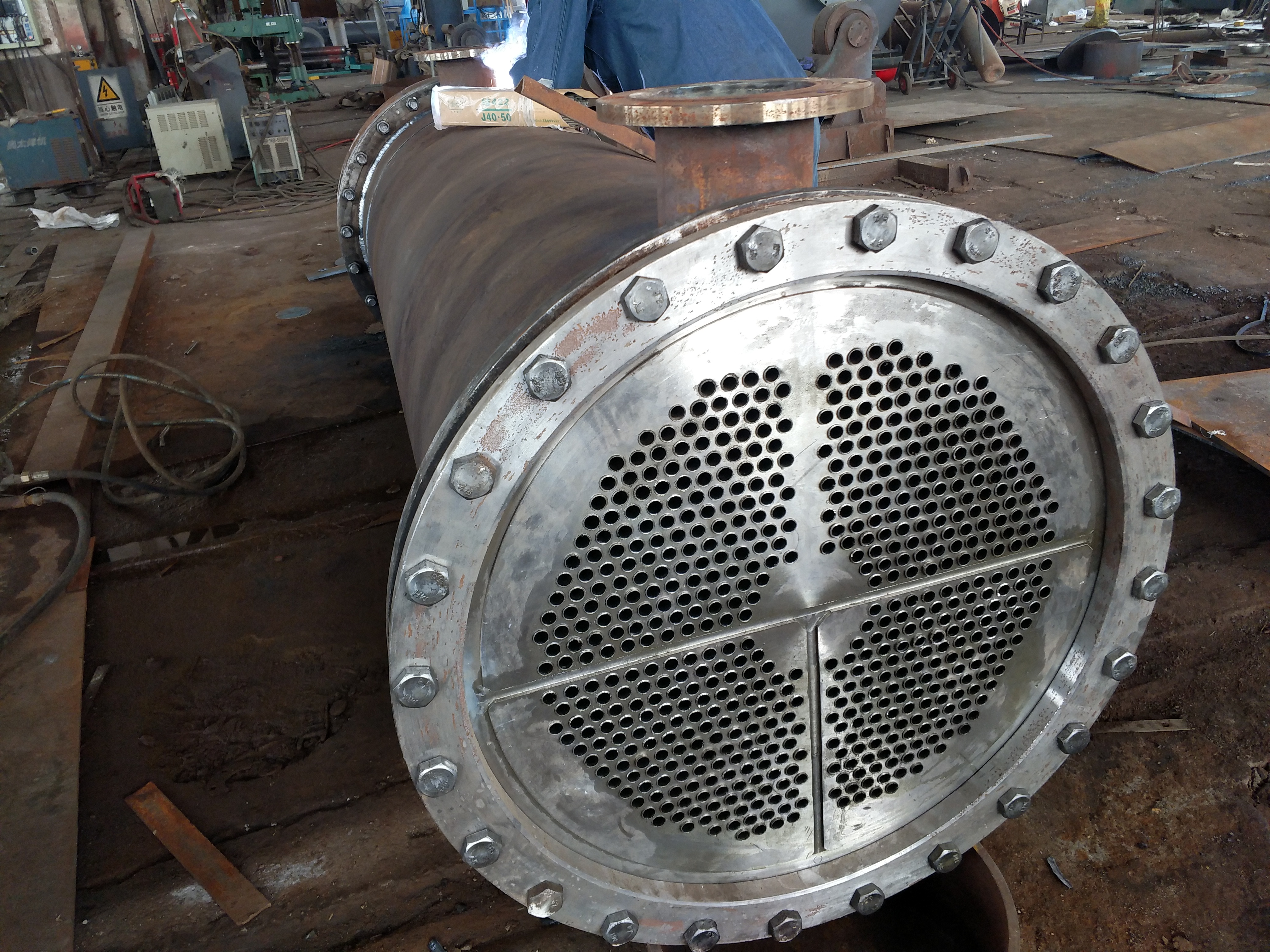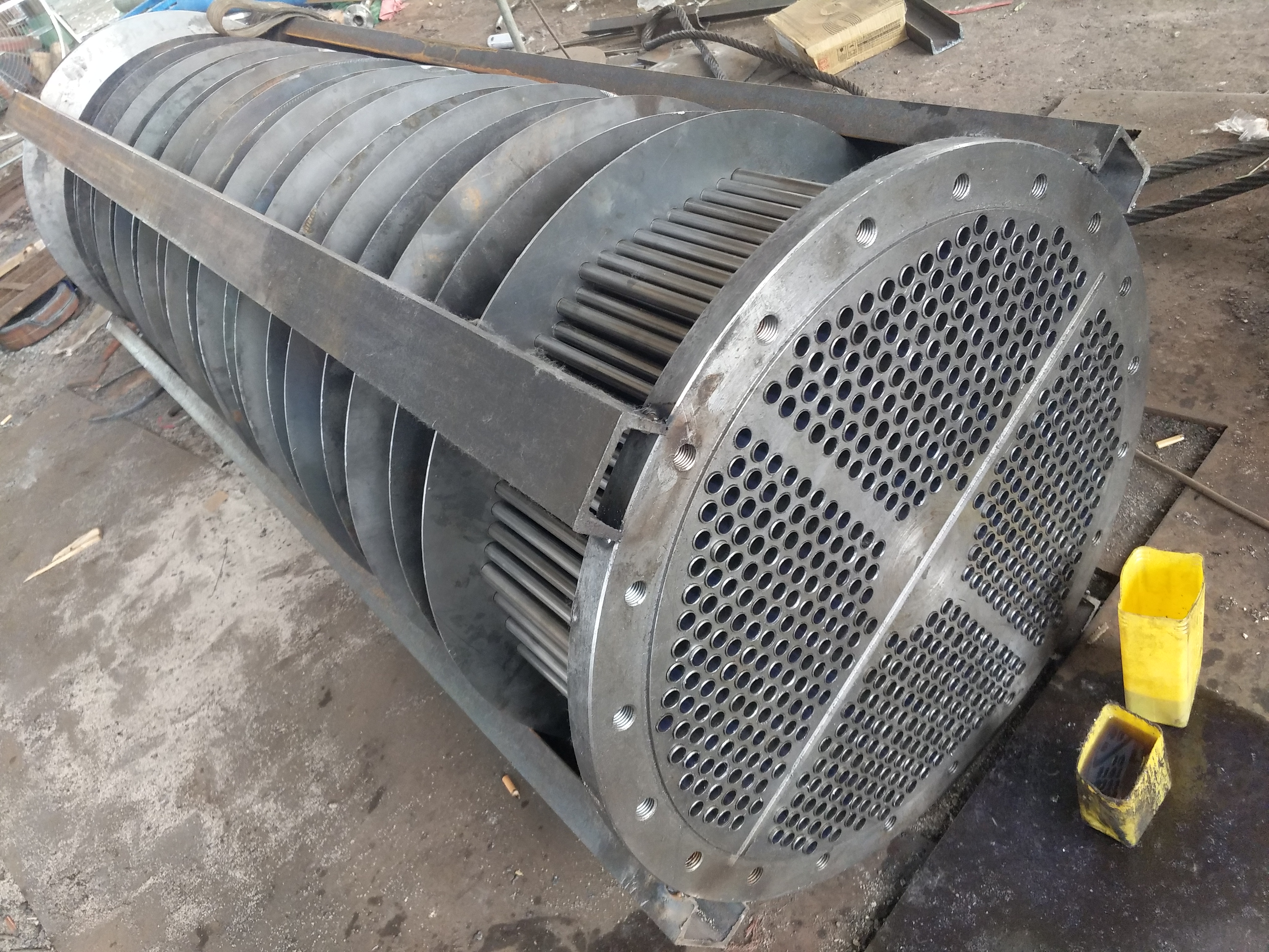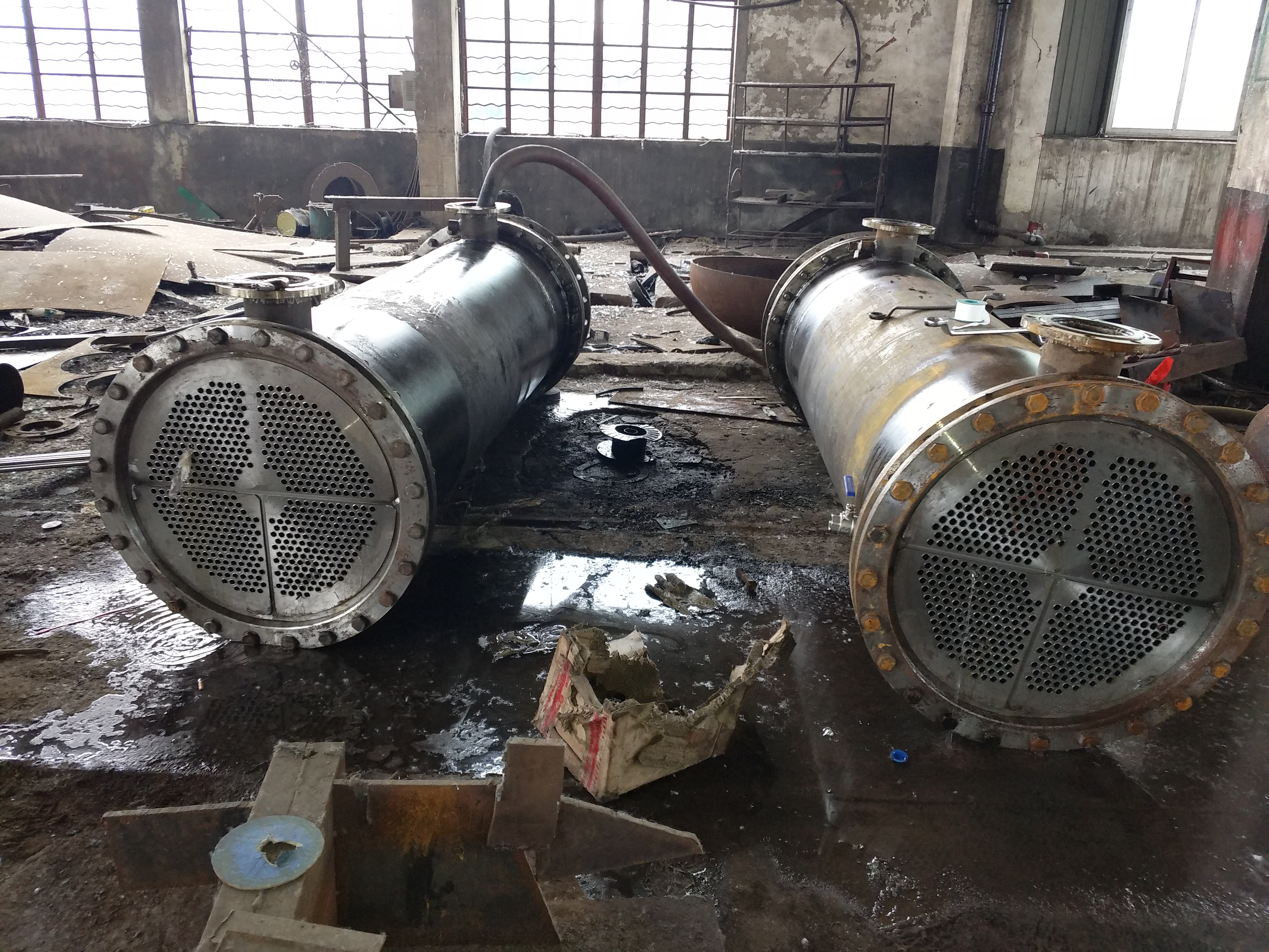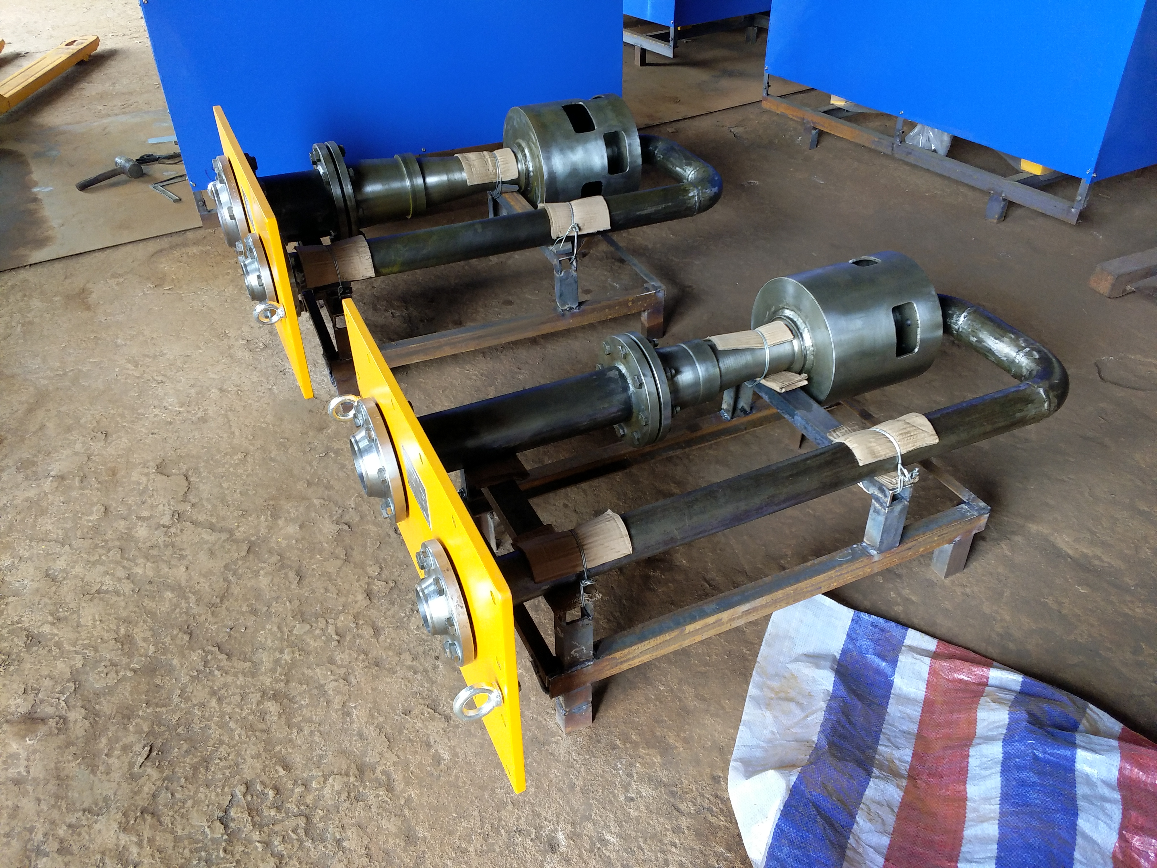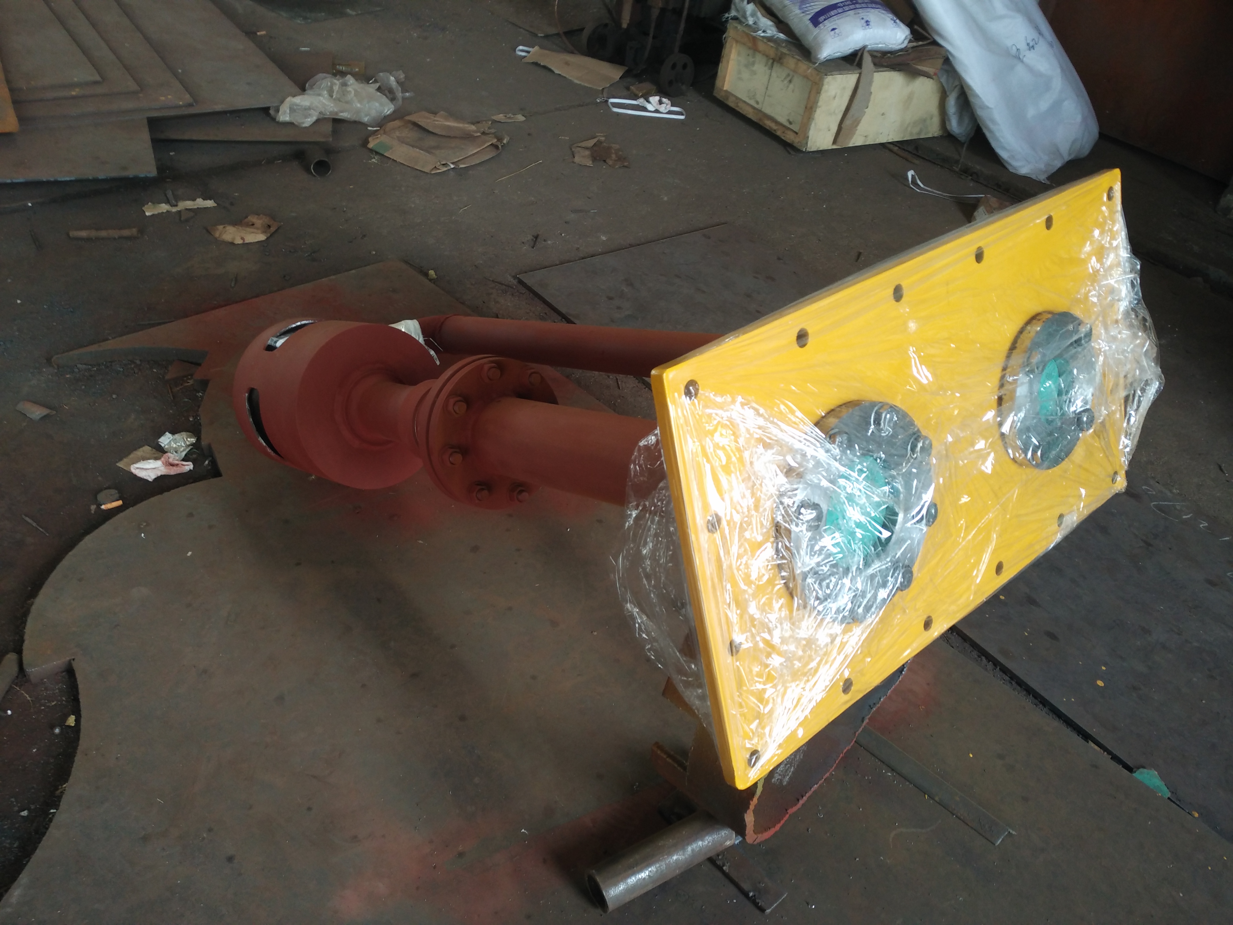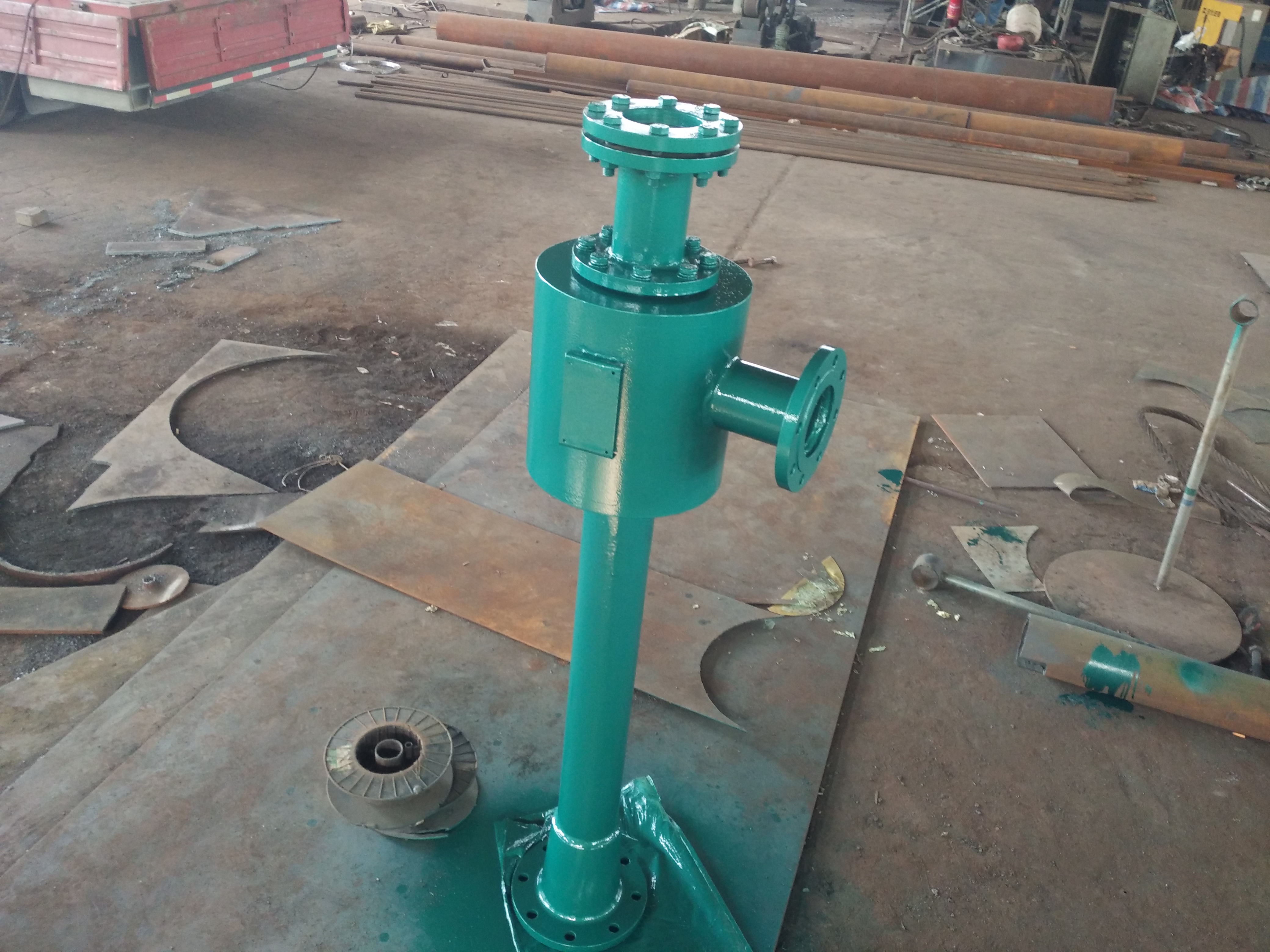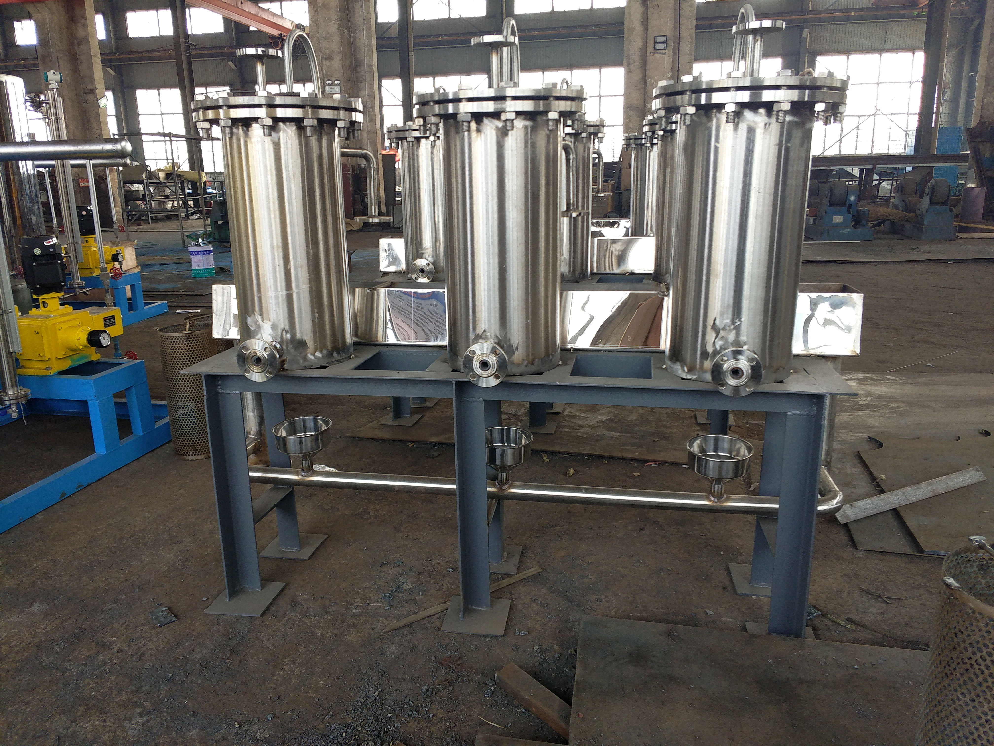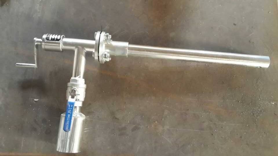
Introduction to the Cooling Cooling Cooling:
The role of a steam-seal cooler is to make the turbine-rear steam seal-trains slightly negative pressure, and the-steam pipes continue to enter the auto seal cooler through-steam pipelines and condense it into water for reuse of the boiler.
The knot of the auto seal cooler-and material:
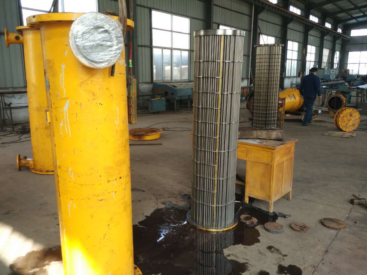
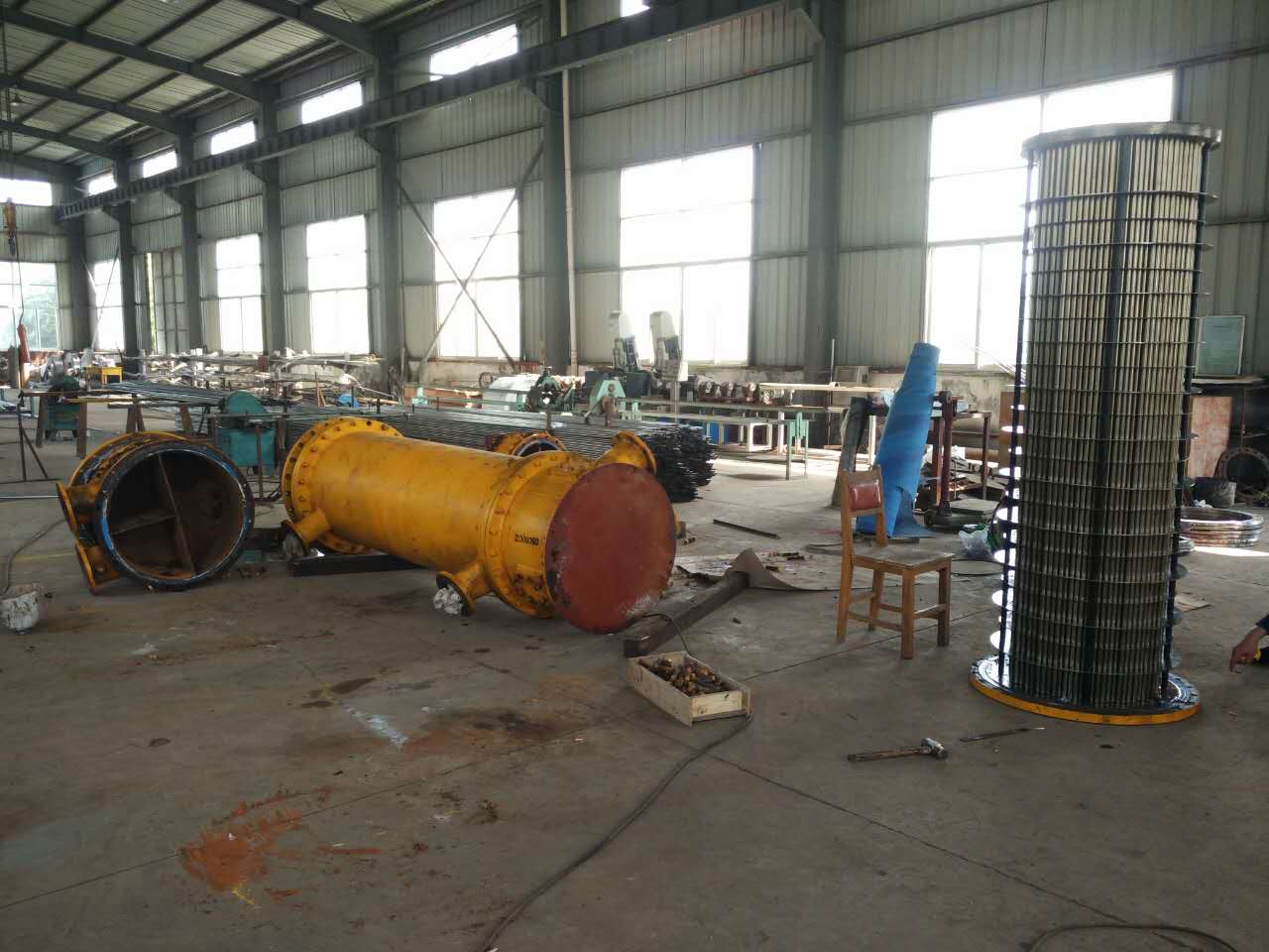
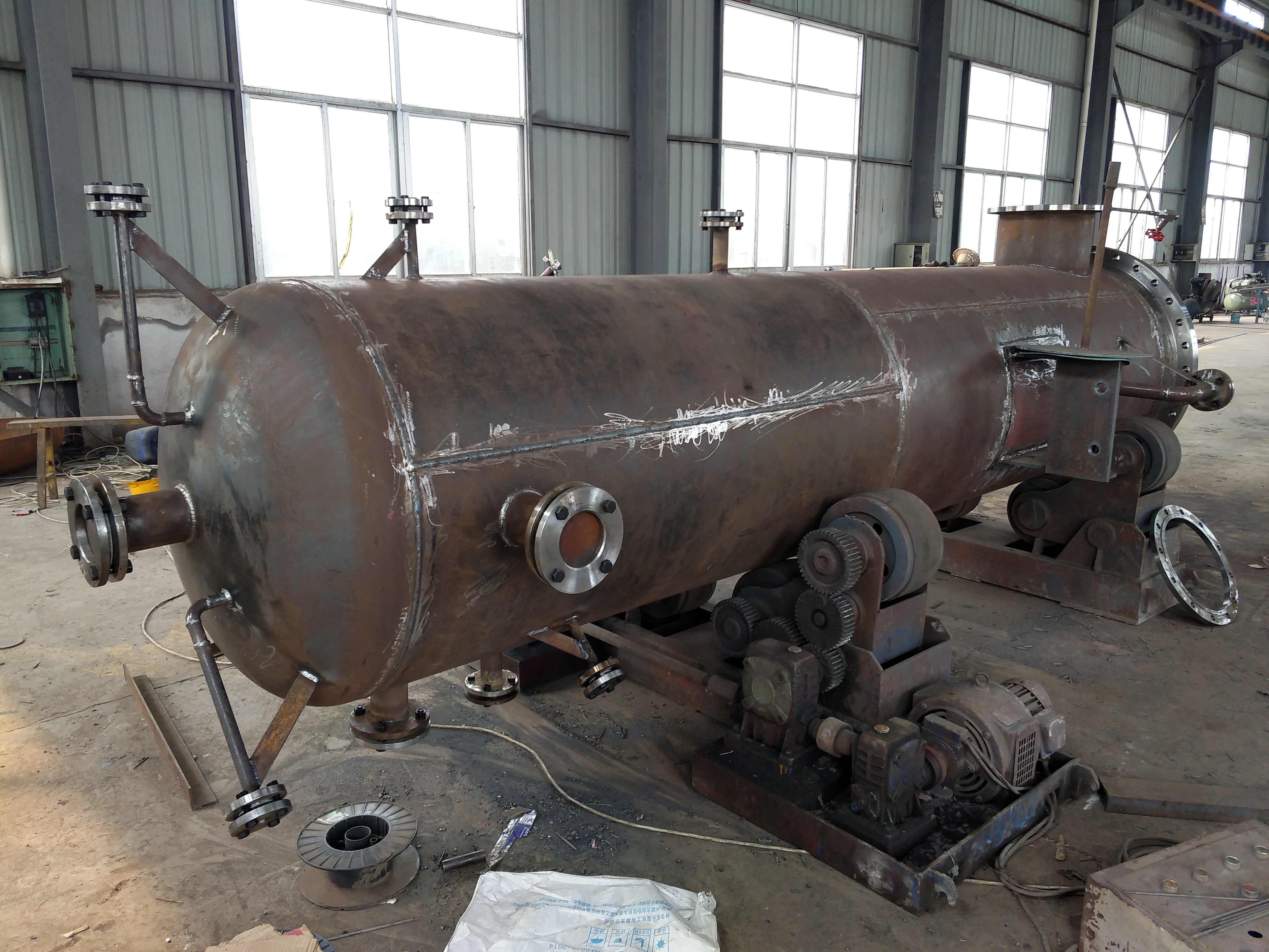
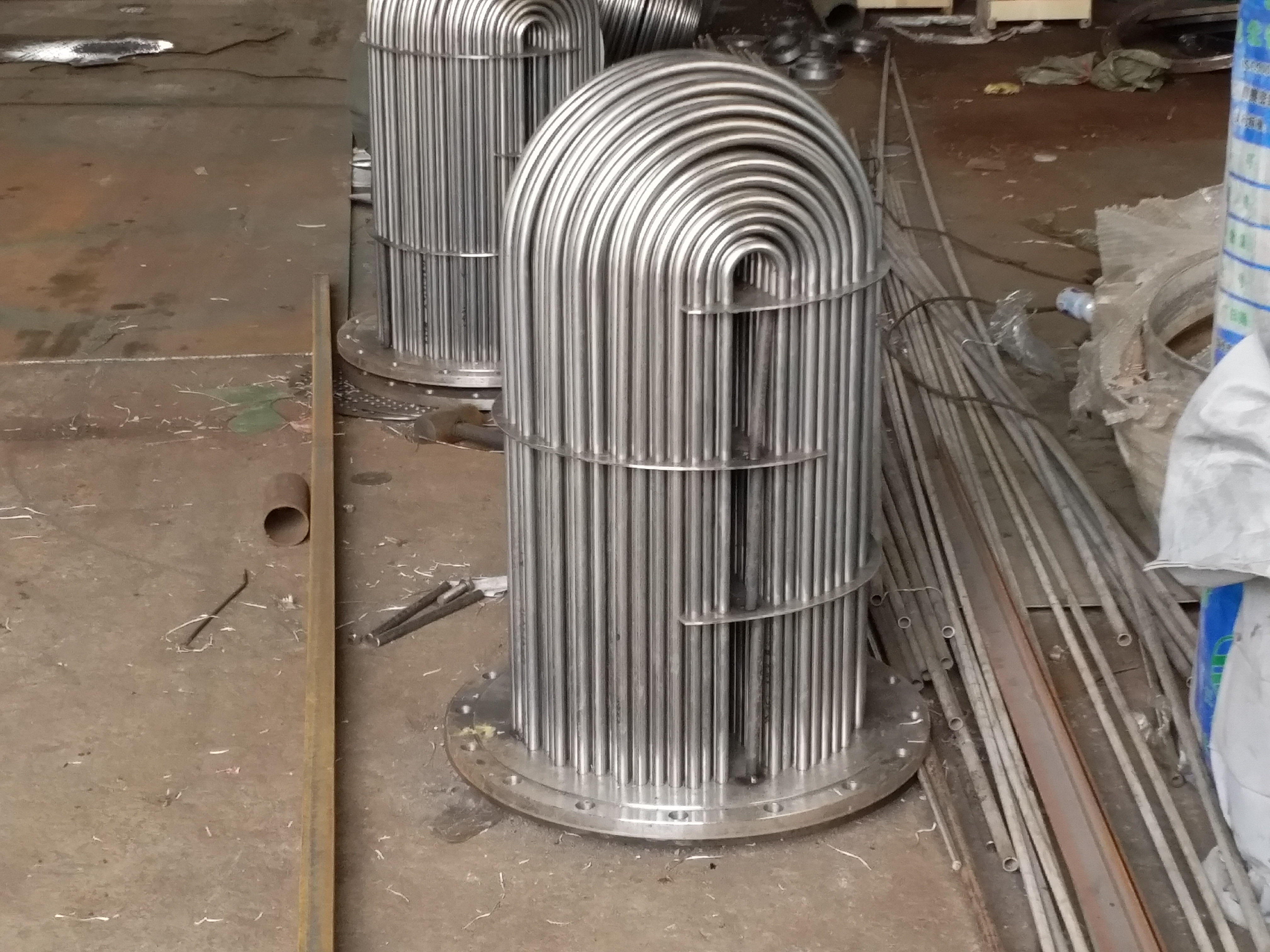
The auto seal cooler is a surface heat exchanger, a horizontal knot-, consisting of water chamber and shell, shell material: carbon steel or stainless steel, pipe materials: stainless steel pipe, copper pipe, etc.
Auto seal cooler knot-:
The water exchanger water side of the auto seal cooler uses four process knots-, its cooling water-enter the water room from the water inlet of the water seal cooler, and then flow into the tube of the shell-when the cooling water is in the heat exchange pipe When flowing, heat exchange with steam in the shell (steam side). Cooling water absorbs a large amount of steam condensation heat, rising water temperature,-later enter the export water room, and overflows the auto seal cooling through cooling water exports. Instrument. The steam from the turbine-rear axis seal, through-auto pipeline, enters the inside of the shell from the auto-seal-seal-seal-entrance. The diversion of the steam flowing through the interval between the interval is constantly flowing between the heat exchange pipes of the tube, and the heat exchange is performed. When most of the steam passes through the outer wall of the heat exchange pipe, it releases a large amount of heat and condenses into water. Excessary from the hydrophobic port and enter the hydrophobic pipeline. Because-steam-some of the air that cannot be condensed, in order to make-steam continuously pass-auto pipelines and enter the auto seal cooler, you need to pull out the gas, and through the steam injection, the air and residual steam are discharged to the atmosphere.
Step installation steps for auto seal cooler:
1. -Can the base of the vapor sealing the cooler is qualified and clean up the foundation surface.
2. Hall out of the auto seal cooler on the basis, adjust the level and elevation position.
3.-Check the location of the cooling device and whether the interface position is correct.
4. Fixed equipment (secondary pouring).
5. Connect the pipeline and electricity-.
Precautions for the installation of auto seal cooler:
1. The equipment should be placed on the flat venue.
2. When hanging, the second-sided steel wire rope is on the outside of the equipment support, and the force is uniform.
3. Equipment should be avoided-the effects of external or external torque.
4. When connecting the pipeline, consider the displacement of the device and the displacement of the pipeline. All interfaces (including valves, instruments, instruments, etc.) should be cleaned up. Disassembly seal (including sundries such as steel plates, cardboards, etc.) should be removed to prevent the pipe port from blocking the mouth.
5. Electric-parameter requirements.
6. Start operation-, the whole system-to be cleaned to prevent the blockage and (or) damage of certain equipment, the pipeline-should consider the use of filters.
7. All takeover-the cover should be uniform-seal to prevent leakage.
8. Tie-conduct-seal-test and eliminate leakage-.
9. Rehabilitation, installation instrument, instrument.
Starting and shutdown:
The operation of the auto seal cooler should pay attention to the following basic steps:
1. British-the exhaust pipe is unblocked-block.
2. The condensate water and hydrophobic pipeline of the cooler should be unblocked.
3. Turn on the cooling water into/outlet valve so that the cooling water circulates in the cooler.
4. Open the auto seal cooler into the steam valve and start the injection.
5. In order to protect the cooling tube of the cooling cooler, the pump should be parked in the auto seal cooler
|
|
|
|
|
|
|
|
|
|
|
|
汽封加熱器型號 | QF-8 | QF-8/10 | QF-10/12 | QF-10/12 | QF-14 | QF-17 | QF-25 | QF-30 | QF-45 | QF-65 | QF-70 |
| 8 | 18 | 22 | 30 | 14 | 17 | 25 | 30 | 45 | 65 | 70 |
水測壓力MPa | 0.392 | 0.392 | 0.392 | 0.392 | 0.588 | 1.372 | 1.47 | 0.98 | 2.45 | 1.57 | 2.45 |
| 0.49 | 0.588 | 1.176 | 1.57 | 0.093 | 0.093 | 0.093 | 0.095 | 0.088 | 0.073 | 0.093 |
管徑外/內(mm) | 15/13 | 15/13 | 15/13 | 16/13 | 15/13 | 16/14 | 19/17 | 15/13 | 19/17 | 16/14 | 19/17 |
設備-量t | 0.43 | 0.52 | 0.67 | 0.84 | 0.5 | 0.8 | 1.2 | 0.71 | 1.6 | 2.0 | 2.1 |